Measurand Voltage
Calibration of the measurand "voltage" is our core business
A distinction is made between different types of voltage:
- DC voltage
- AC voltage
- Impulse voltage
- Lightning impulse voltage
- Switching impulse voltage
Different measuring systems and measuring instruments are manufactured and calibrated according to the different voltage types. A high-voltage divider is connected upstream of the measuring instrument for measurement of high voltages. Depending on the type of high voltage, either a specialised high-voltage divider for a particular voltage type or a universal high-voltage divider for several voltage types is used. The divider can be qualified as follows based on the measurand:
- DC voltage divider
- AC voltage divider
- Divider for lightning impulse voltage
- Divider for switching impulse voltage
- Impulse voltage divider (intended for both forms of impulse voltage)
- Universal voltage divider (intended for several or all types of voltage)
Depending on the measurement task, measuring instruments with one or more methods of evaluation can be used:
- Peak AC voltage value
- Average DC voltage value
- Peak-to-peak voltage of the AC voltage
- RMS value of the AC voltage
- Form factor of the AC voltage
- Digital recorder for impulse voltages in particular
- Oscilloscopes for impulse voltages in particular
Principles of measurement and measured values
Different designs of high-voltage divider are required depending on the type of voltage and the parameters and measurands that are to be measured. For this reason, it is important that the parameters that are to be calibrated are accurately described.
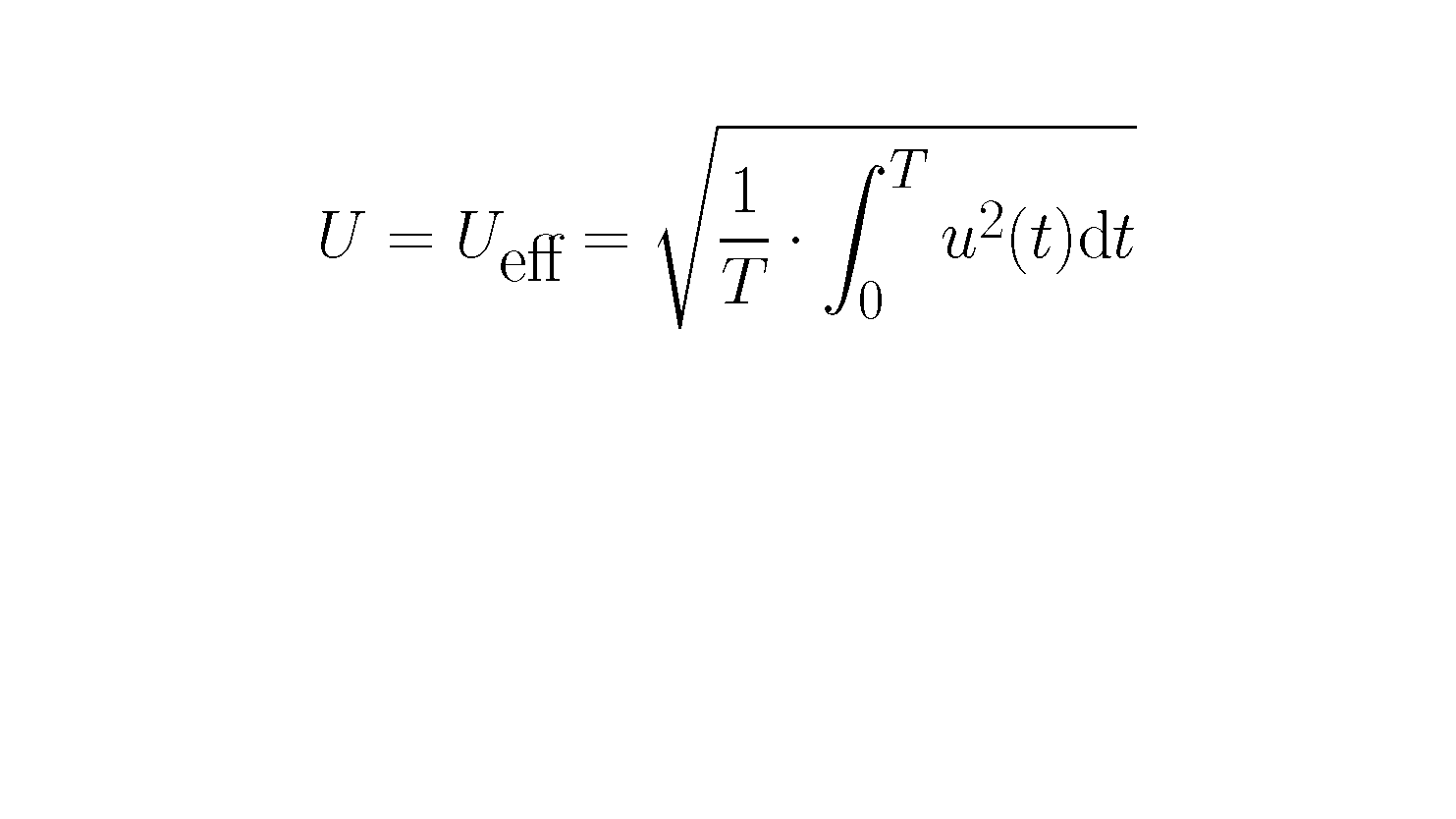
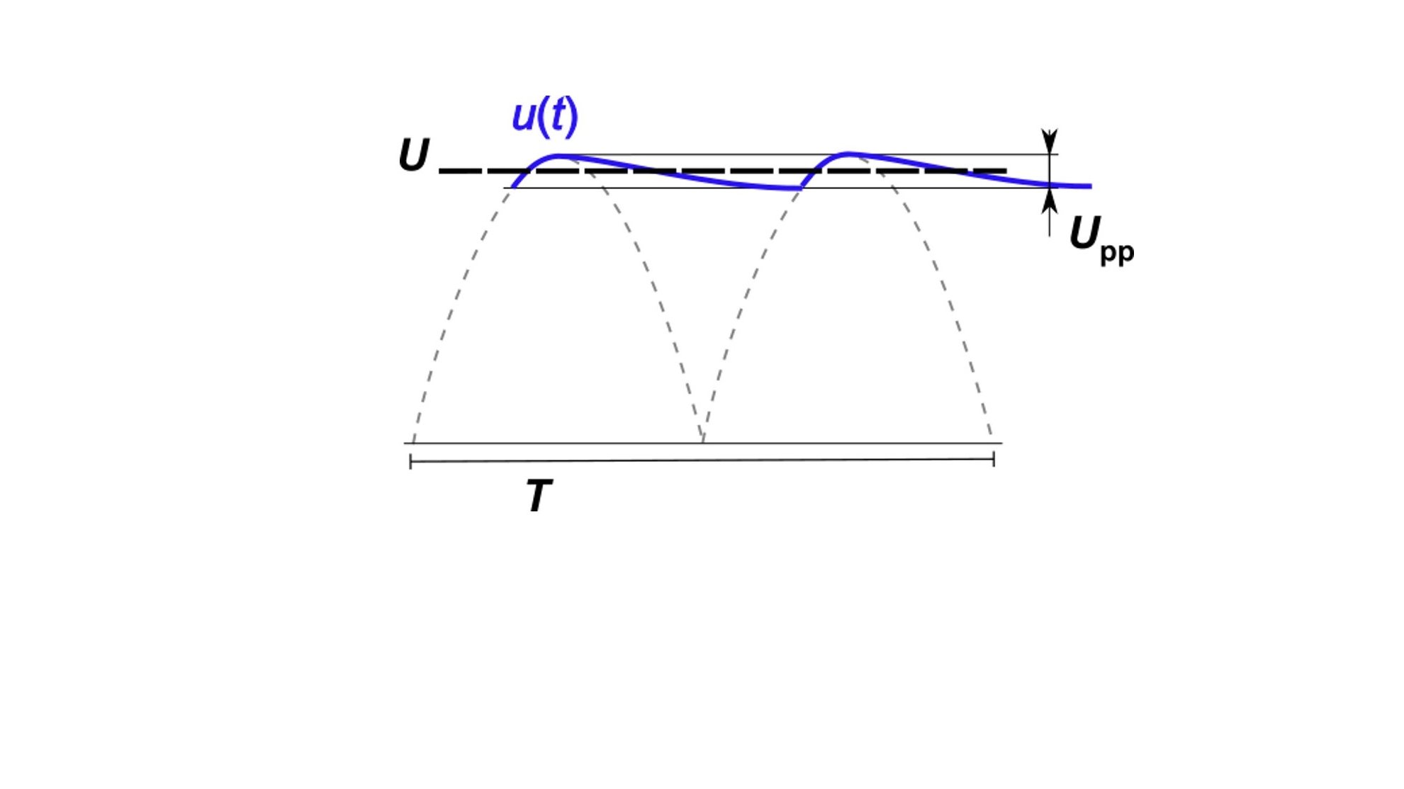
The effective value (or RMS, root-mean-square value) for the AC voltage U is a familiar concept to most people. Whenever a value relating to AC voltage is stated, this refers to the RMS value of the AC voltage. The RMS value is defined as shown.
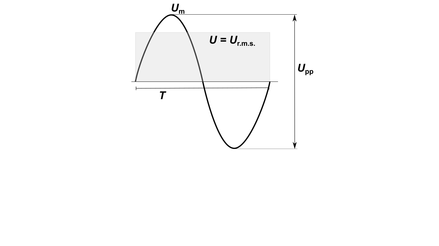
For a sinusoidal AC voltage the value is calculated as U = Ur.m.s. = Um /√2.
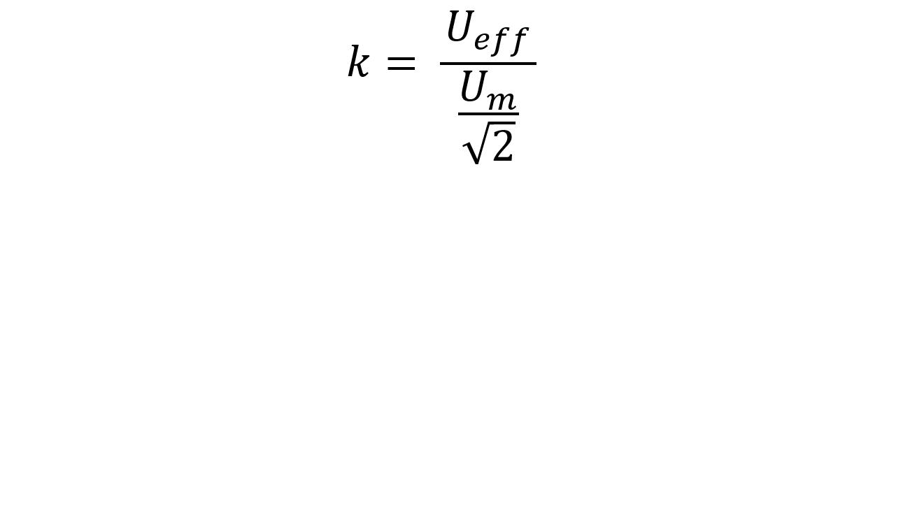
However, since the test specimens are subjected to extreme loads in the high-voltage tests, the peak value of the AC voltage Um is also often required. The form of the AC voltage is also covered by the test in the form of a factor known as the distortion factor k.
Another value that is used more rarely is the so-called peak-to-peak value Upp. Other parameters for AC voltages are the frequency f as the reciprocal of the period T. The form of the AC voltage is also included as a factor in the test. Numerically, the deviation from the sinusoidal form of the AC voltage is expressed with the form factor.
The average value of the DC voltage U is the most common measurand. In most cases this measurand is sufficient. Another parameter for the testing of DC voltages is the ripple. It is often incorrectly assumed that all DC voltage measuring systems can also always measure the ripple. In order to measure the ripple it is necessary to record the changes over time of u(t). Not all DC voltage measuring systems are suitable for this. The requirements for DC voltage measuring systems that can record the ripple are defined in the standard IEC 60060-2.
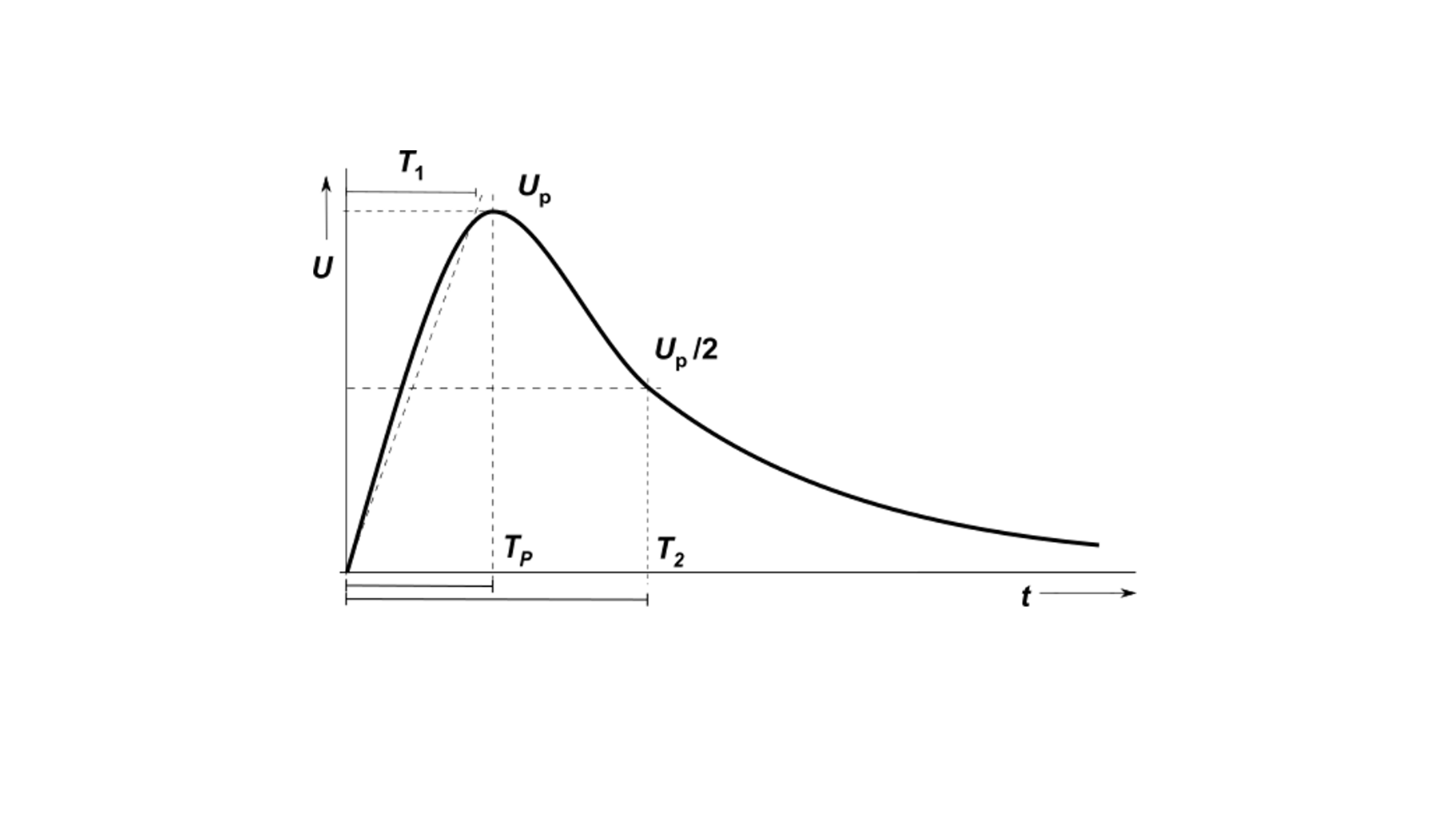
Impulse voltages are characterized with general parameters:
- Magnitude of the voltage at the peak Up
- Time parameters for the rise T1, peak Tp and time to half valueT2
Further parameters are specific to the voltage wave. Even the determination of parameters with the same name differs depending on the particular wave form. The best-known forms of impulse voltages are:
- Lightning impulse voltage
- Switching impulse voltage
Calibration using the comparison method
Calibration using the comparison method
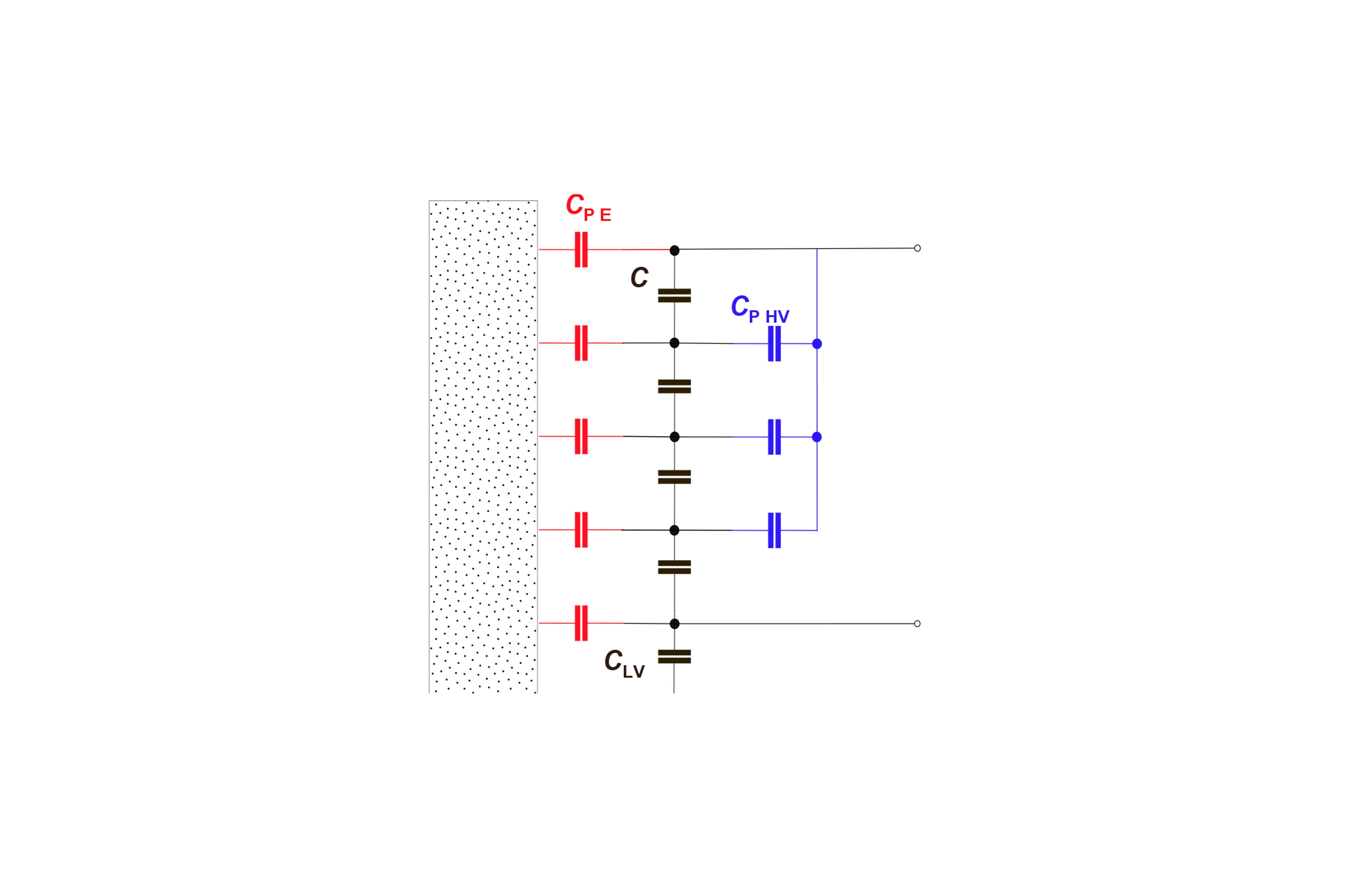
The main parameter of a divider is its scale factor. The scale factor can be calculated from the main components, for example the main capacitances C and the low-voltage capacitance CLV. However, in addition to the known main physical properties other parasitic parameters of the divider play an important role during operation. The parasitic parameters contribute to a lesser or greater margin to the distortion of the scale factor. Comparison measurements are preferred as a calibration method because all parasitic parameters can be detected in comparison to the known standard. The following are some of the most important parasitic parameters:
- Temperature influence
- Parasitic capacitances to earth connections CPE and to high-voltage feeds CP HV. The effect is explained in the diagram on the right.